
CONVERTING A TONE DIALER INTO A RED BOX
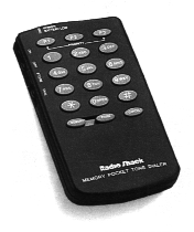
Using a Radio Shack Tone Dialer is by far the most popular method of building a red box in the 90’s. There are several different variations of the tone dialer red box, all of which will be explained below.
Many people ask me what the legitimate use of a tone dialer is. Tone dialers are used to access touch tone voicemails and voice menus when you’re calling from a rotary dial phone. Even though rotary dial phones are very close to obsolete now, tone dialers still come in handy to store commonly dialed phone numbers in. They can also be useful to a phreak when a phone disables it’s keypad or has a lock on it to prevent long distance dialing.
The biggest problem I’ve run into while explaining this method is the different variations of tone dialers themselves. See, Radio Shack knows that certain people buy these tone dialers for the sole purpose of screwing the phone company. They’ve come out with two new models of the “33 Memory Pocket Tone Dialer” in just the last decade.
The first upgrade was a definate improvement for the underground. The circuit board remained the same but the outer casing was sleeker looking, a bit smaller, more water proof and made it easier to install the over-sized red box crystal.
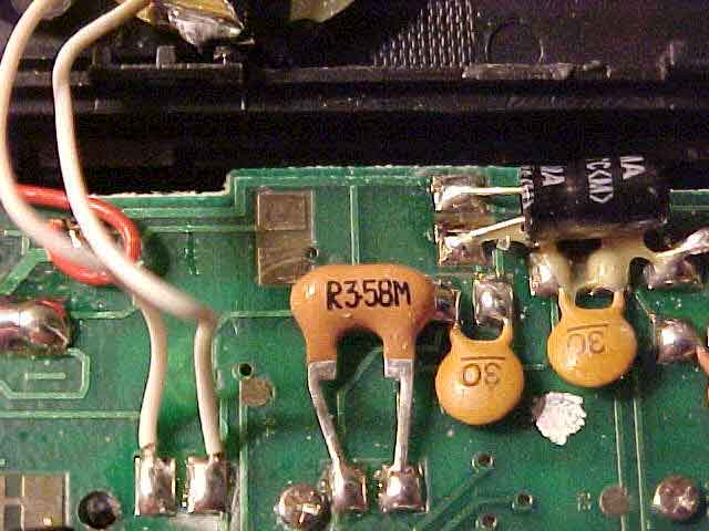
 But in the last year or so (1996-1997), they’d upgraded once again, this time to stop us evil phreaks from modifying it for illegal use. Personally, I’ve never encountered one of these new models so I can’t really tell too much about it except for what I’ve heard. Supposedly, the crystal still exists but they’ve disguised it as a capacitor. I’ve heard a dozen different stories about the placement of this new capacitor so I can only say that most people have told me it’s in the same place as the old crystal always was and it has Z3.58M written on it. The picture here attempts to show you a real picture of the circuit board and the new crystal, although it’s hard to see. Click on the picture for an enlarged view or click here for an extreme closeup view. (big thanks to dominicky for these new pictures!)
Below is a list of the different kinds of tone dialers available from Radio Shack. If you have further questions about the different models, Radio Shack can be contacted by dialing 1-800-THE-SHACK.
43-145 This is a cheap tone dialer with no memory presets on it. These dialers cost $16.99 and can be modified, but without the memory presets you won’t be able to make quarter tones, just nickels which can be a little time-consuming. But if you want to save a lousy 10 bucks, this is the way to go.
43-141 This is the original 33 memory pocket tone dialer. This model was brown and very ugly-70’s looking compared to the newer models. This one will work for red boxing just as good as the new ones. Radio Shack stopped making this model in 1994.
43-146 This is the current 33 memory tone dialer which sells for $24.99. Both the newest “hack-proof” model and the 1995- model share the same catalog number, contrary to popular belief. The crystal in this model has been disguised to trick people into thinking that you can no longer use it for illegal purposes.
MODIFYING A TONE DIALER
These is the original plans for building a red box as described in 2600 magazine by Noah Clayton. This section is taken from PLA’s issue 02.
You will need:
Place the dialer on the table keypad side down and speaker side up. Remove the battery cover and all the batteries. Use the phillips screwdriver to remove all four screws on the back of the dialer. If you’ve got the new model, there will be six screws. Now slide the flathead screwdriver along the side to separate the two halves of the dialer. Slide the
speaker half underneath the keypad so you don’t break off the speaker wires.
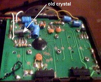
On the left hand side down near the battery compartment, you’ll see a silver cylinder looking component. This is the crystal you want to remove. Pull it up with your fingers and break away all the glue that’s holding it down. Use your soldering iron and un-solder it from the circuit board. You can throw
this crystal away as it has no real use in life.
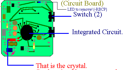 Now the hard part. The new crystal you’re putting in is twice as big as the old one so it’s kinda hard to get it in there. There’s a few capacitors that you can bend over to make some more room. You’ll also have to bend the leads to your new crystal inward a little. Solder the new crystal in place of the old one and you’re all set. Snap the two casing halves back together being careful not to pinch any wires. Put the screws back in and insert your three AAA batteries. The diagram on the left, shows you what the circuit board looks like. Click on it to see a bigger picture.
A good idea is to wrap the crystal with scotch tape or electrical tape. This will prevent contact with other components since the crystal is so big. You could also simply put a piece of paper under the crystal. Before you put the screws back in, you might want to put the batteries in and make sure that when you press buttons, the red box is making noise. If it isn’t adjust the crystal slightly and try again.
One additional thing you can do it totally remove the LED light. The only thing this light is good for is running down your batteries really quick. If you use the unit without the light connected, you NEVER have to turn the unit’s power off and the batteries will last for a few years before you need to replace them. When doing this, I also solder the power switch into the “on” position and remove the switch itself. But only attempt all this if you’re comfortable with your soldering skills.
PROGRAMMING YOUR RED BOX
Now that your dialer is put back together and the batteries are in, test it out by hitting a few keys. You should hear high-pitched touch tones. The “star” key on the dialer is your coin key. By hitting this key quickly one time, you create a nickel tone. Two times makes a dime tone and five times equals a quarter tone. Nobody can hit the button fast enough to make a quarter tone so you have to program 5 hits into one of the memory locations.
You’ll be using the three priority buttons on the top of your unit. P1 will be your quarter, P2 your dime and P3 will be the nickel. So here’s how to do it:
you’ve disconnected it.
Try pushing the priority buttons now. Each one will emit a different high-pitched chirping noise. This is what the phone hears when you deposit money into a pay phone. If you’ve ever red boxed with a taperecorder or heard the actual pay phone tones before, you’ll notice that these tones are slightly slower than the real ones. Don’t worry, the pay phone can’t ever tell the
difference and it’s rare to find a live operator who can.
If you want to program in $1.00, it’s best to use this programming string:
MEMORY, *, *, *, *, *, 0, *, *, *, *, *, 0, *, *, *, *, *, 0, *, *, *, *, *,
MEMORY, P3.
This will make $1.00 go in a lot faster than if you’d used the PAUSE feature because “0” is being used as a substitute for PAUSE. (The phone just ignores
the 0.) Don’t use this string on a live operator, though! Thanks to Even in California for giving me that idea. Using the P3 location will replace your nickel tone.
TROUBLESHOOTING
One of the most common problems I’ve had with my red boxes over the years, is that the tones will stop working in the middle of trying to put in your money
or they’ll break up, giving you a live operator. This could be because you did a bad job soldering the new crystal in. More commonly, the contacts on the
power (or the DIAL/STORE switch) have bent the wrong way, causing them not to touch the circuit board anymore.
To fix that, open the unit and bend the contact in the switches out a little. Not too much or they’ll break when you use the switch. If you’ve removed the light in your unit, there’s really no reason to ever turn it off so you could glue the power switch into the “ON” position or remove the power switch and solder the appropriate contacts into the “on” position.
MAKING A RED BOX/TONE DIALER COMBO
If you’re the type of person who just has to have a tone dialer AND a red box then you can have both without having to carry around two seperate
units.
crystal and in the middle solder two small wires, each about 4″ long.
Pretty easy, aye? You can put the two wires through one of the vent holes in the back of the unit. On my red box, I took the plastic piece off the back of the battery cover (You know, where you’re supposed to write the memory numbers?) and electrical taped the switch down. It actually doesn’t stick out hardly at all and looks fairly professional.
Now you can switch between red box and tone dialer. You can store your stolen calling card numbers in the other memory locations or use the touch tones to get free calls on those damn privately owned pay phones.
THE STEALTH-COMBO BOX
The following article was written by DeadKat of CoTNo and is, in my opinion, the best ever variation of the original tone dialer design. You can pick up this article and other issues of CoTNo on the FTP.FC.NET site. Highly recommended.
Ever since the original Rat Shack Red Box mod was printed in 2600 Magazine, there has been an explosion in red box use. Red boxing is still one of the primary topics of discussion on alt.2600 years later. The Radio Shack Tone Dialer mod was one of the first boxes I ever built and has proven to be the most useful of all the boxes I’ve experimented with.
For years, though, I’ve played with the original design in order to improve it. My favorate variation of the original plans is what I call the Stealth-Combo box. It is based on the original design, but makes use of mercury switches to allow the use of both DTMF’s and ACTS tones. In other words it combines the functions of the red and white boxes.
The reason its called ‘stealth’ is the fact that when the dialer is held in its normal position, it will produce touchtones as if it were un-modded. When held ‘upside-down’ it is capable of producing tones similar to the Bell ACTS tones that emulate a quarter being dropped into a payphone. This design not only gives you both features, but leaves the box looking and
seemingly acting ‘normal’.
Following are the complete steps to building the Stealth-Combo box that I demonstrated at the Denver 2600 meetings. These instructions assume that you have some experience working with electronics. If you don’t, practice a bit before you go cutting up your $30 tone dialer.
Parts List
Recommended Tools
Steps
1. Remove the 6 screws securing the back of the Tone Dialer to the front.
Four of the screws are underneath the battery cover.
2. Gently pry off the back being careful not to break the four wires that
connect the speaker to the circuit board. Lay the back cover to the side
of the dialer. You should now be looking onto the back of the dialer’s
circuit board.
3. Locate the original crystal (silver cylinder) on left side of the circuit
board. Carefully cut the crystal off the circuit board as close to board as
possible. Use needle nose pliers to pull the crystal loose as it is held in
place with rubber cement. Be careful not to crush the crystal!
4. Measure out 2 pieces of wire that are long enough to go from the
original crystal solder points, around the edge of the dialer, to a point
on the lower right side of the circuit board. Solder one end of the wire
to the lower original crystal solder point and the other end to a lead on
the original crystal (keep the leads on the crystals as short as possible).
Solder the other wire to the other lead on the crystal but _not_ to the
circuit board. Leave it hanging for now. Use tape to insulate the crystal’s
leads.
5. Route the wires around the edge of the circuit board on the _underside_ of
the circuit board. You may have to remove the circuit board to route this
sucessfully. The circuit board is held in place by 6 philips screws down the
middle of the board. Glue or tape the crystal into place on the lower right
side of the circuit board on the underneath side (the keypad side). This
will leave us more room on the circuit board for the swithches.
6. Locate four green capacitors on left edge of the circuit board. Cut off
the second one from the bottom as close to the circuit board as possible.
Important! Make note of which lead on the capacitor went to which solder
point. Unlike crystals, capacitors are directional and if you reverse the
current, it will fry.
7. Glue or tape the capacitor to the empty spot on the upper right side of
the circuit board next to the LED.
8. Solder wires from the leads on the capacitor to the original solder points
of the capacitor. Run the wires along the edge of the circuit board and
insulate the capcitor’s leads with tape. You have now moved the capacitor and
made room for the first switch.
9. Glue or tape the first switch on the left side of the circuit board
where the capacitor used to be. Carefully push the upper two green
capacitors to the right to help make room for the first switch. Orientate
the switch’s leads down.
10. Solder the free end of the wire that runs to the original crystal
to one of the leads on the mercury switch. Solder a wire from the other lead
of the mercury switch to the upper solder point of the original crystal. The
circuit should now go from the upper solder point through the switch to
the original crystal and back to the lower solder point.
11. Test your work by putting the batteries in the dialer holding the slide
switch which turns on the dialer in the on posistion. The LED should come
on. If it doesn’t, check your work. Make sure that the circuit is complete
and the leads aren’t grounding on anything. Hold the dialer in an upright
position while holding the switch on and press some buttons. You should
hear touchtones. If not, make sure you haven’t broken any of the wires to
the speakers.
12. Locate the yellow capacitor on the lower right side of the circuit board.
Gently pry the capacitor loose with needle nose pliers and flip the capacitor
over. Insulate the leads of the capacitor with tape so that it doesn’t come
in contact with the resistors which it is now partially laying on. This will
leave a nice open spot on the circuit board for the rest of our mods.
13. Look at the back cover of the dialer. You will notice that on the lower
left side of the back cover is some space about the size of a crystal. How
convenient! Remove the small screen on the lower left side that covers a
small opening in the cover.
14. Glue the new crystal into the spot where the screen was with the leads
facing out. The crystal will stick out the hole a little bit, but that won’t
hurt anything.
15. Glue or tape the mercury switch in the space to the right of it with
the leads oriented up.
16. Solder wire from the new crystal to one of the leads of the mercury
switch. Solder a wire from the other lead of the new crystal to the lower
solder point of the original crystal. Make the wire to the solder point
as short as possible with the case open. Insulate the leads with tape.
17. Solder a wire from the remaining lead on the second mercury switch to
the upper solder point of the original crystal.
18. Test your dialer once more. This time hold the switch in the on position
while the dialer is upside down and press the keys. You should here the
touch-tones in a much higher key now.
19. If everything has tested out, then close up the box. This is probably
the most difficult step of all. You must have the mercury switches located
just right, or it won’t close. Also you must place the wires which run from
the back cover away from the the components in order to optimize space.
Carefully close the box, but be warned, it takes quite a bit of pressure to
get the box closed. You may want to have a friend help you hold it closed
while you screw the screws back in. You may break a switch or two before
you get it right. Be very careful with any spilled mercury since as Karb0n
once told me, “Dude! That shit will make you go insane!” You must get the
case closed all the way, or the on switch will not make contact. This step
can be very frustrating, but once you get it closed _and_ working, don’t
ever open it again!
(C)opywrong 1994, DeadKat Inc. All wrongs denied.
FINDING A 6.5xxx crystal
Any 6.5 crystal will work in a tone dialer, whether it be 6.5 or 6.5536 or whatever. Here are a few places to order crystals from:
Radio Shack. They will insist that they don’t carry them but you have to tell them they need to special order it from their catalog. Make the guy search for it until he finds it. The crystal costs around $7 and takes about two weeks to arrive either at the store or in your mailbox.
Mouser Electronics. Their number is 1-800-346-6873 and they cost about $2.00 apiece. Ask for stock #520-HCU655-S which is a 6.5536MHz crystal. Or you can order them online from www.mouser.com.
Newfound Radio Shack Tone Dialer Takes Phreaking World By Storm

Cat. No. 65-721
Inside sources in the electronic-store giant Radio Shack informed me today of an acquisition of an advanced tone dialer. The dialer, which is dubbed “Personal Data Directory with tone dialer,” presents new possibilities for the phreaking community, which has heretofore used Radio Shack “33-Number Memory Pocket Tone Dialers” (Cat. No. 43-146) to create a device called a Red Box. The new tone dialer’s catalog number is 65-721. The newer dialer’s advantages over No. 43-146 include an LCD display, requires one less “AAA” battery, stores 75 entries which include a name and two phone numbers, and a built-in calculator, to name a few.
When I recieved this information, the Radio Shack Sales Associate also informed me that there was only one more dialer available. So, after a mad dash for my wallet and keys, which took an hour and a half, I rushed down to the store and bought 65-721. My luck was very great today; apparently Radio Shack is having a Christmastime sale, so the normally-40-dollar dialer was discounted at the beautiful price of $24.95. I seem to recall paying as much for the normal tone dialer.
I got home and popped the box open and, frankly, the dialer is fantastic sexy keen. It is physically smaller than the regualar tone dialer, but upon inspection of the inside of the unit, there is ample room for a larger crystal than the stock 3.58 — it will be very easy to convert these dialers into Red Boxes. I plan on installing a switch between crystals so I can use the dialer normally. Whether or not the device will properly operate with the 6.5 crystal is unknown (this thing is a little more complicated than your average tone dialer), but I have a feeling it will. And what better way to display your X-mas colors than to build a Red box? Happy phreaking.
Written, photographed and HTML’d 18.56 PM 11.23.97 for NPA by pSYchrowRYthe
I see that this red box is of some age now, does this red box still work now in 2007????
idk maybe, its been 14 years since you posted that message. crazy
Hello, I have one of the original tone dialers (43-141). I am wondering if these are worth anything now? This one is unmodified, has original box, owners manual and looks brand new.
i was also wondering if is still possilbe to make a redbox now in 2007 since the original ones are kinda old
yes, in 2007 AND 2008 you can still make a redbox and a redbox will still work.
the problem here is with the operative words you’re using. you’re asking the wrong questions.
you can still build a redbox today if you can get the right parts. all the links on this page will still get you to the right parts manufacturers and i’ve seen radioshack tonedialers on ebay.
a redbox will still work because for a redbox to work all it has to do is produce the tones.
if you want to know if you can still use a redbox to fool a payphone you are out of luck
That’s wrong.
Here in New York, red boxes still work.
I was in the Marines in 1994 stationed at 29 Palms attending the communications electronics school. Guys in my class brought me one of these and asked me how it worked and I told them. Next thing I knew, they were everywhere. Eventually, the did a base-wide “health and comfort” inspection, and found a great many red boxes. I got ratted out and fingered as the mastermind, even though I only used one the same as everyone else. I stood NJP in front of the battalion Colonel and was severly punished. It certainly wasn’t worth the $2.75 phone call.
So… I made a redbox. And it works in Illinois.
And Red-Handed, I want details. How bad were you punished?
That sucks, sir.
Pingback: How To Dial Out | PaperStreet
New Model is 65-721
Stumbled upon this article with a tone dialer. Does anyone have a new/used working one available for purchase (not modified)? My church is in desperate need of the old style to work our hymn boards believe it or not! Any help would be appreciated.
I have one of the olllld school units, model 43-141. Its lost the plastic and paper inserts for the back cover, but the two part plastic battery cover is in perfect shape.
The date code sticker, protected by its location under the battery door, says 8A3, which decodes to August of 1993. It was apparently one of the last units made prior to the revision, and was definitely the last unit on the shelves of my major city in the Southeastern USA.
As a kid the closest crystal I could find was 6.304MHz, and I scoured the local electronics shops and the innards of all things electronic which I disassembled. This was in 1994, pre-internet. Last time I tested it was in 1996, at a payphone which had not yet been replaced/upgraded by Bell.
It does not work on the newer payphones. These newer units only accept input from the microphone after coins have been deposited. The microphone needs to be working in order for the red box to be “heard” by the payphone. If you can walk up to a payphone and pick up the handset and blow into the microphone, if you can hear the sound of your breath in the earpiece, you have a chance of the redbox working on that payphone.
Some of you might be familiar with the saying “it’s close enough for Government work,” referring to how something is’t quite right, but it’ll work in the end.
Well, 6.304MHz is close enough for Bell work!
The tolerances I found, not only between tones but also with timing, are kind of wide…
thank you so much for this amazing site me and my phratr favored this self-complacent and penetration